
User manual
Chapter 1 Jewelry Laser Welding Machine operation principle and structure
1.1 Principle of operation
Jewelry Laser Welding Machine is a new type of welding equipment, which is one of
the important aspects of the application of laser material processing technology.
For the welding of thin-walled materials and precision parts, the welding process belongs to
the thermal conductivity type, that is, the surface of the workpiece is heated by laser radiation,
and the surface heat passes through.
The heat conduction diffuses to the inside, and the workpiece is melted
by controlling parameters such as the width, energy,
peak power and repetition frequency of the laser pulse.
A specific molten pool is formed. It can realize spot welding, butt welding, stitch welding, sealing welding, etc.,
with high aspect ratio, small weld width, small heat affected zone,
Jewelry laser welding machine has fast welding speed, flat and beautiful welding seam,
no need or simple treatment after welding,
high welding seam quality, no pores, precise control, small focusing spot, high positioning accuracy,
easy to realize automation.
1.2 Complete machine construction
1.2.1 Jewelry Laser Welding Machine characteristics
DGW-200 Jewelry Laser Welding Machine maximum laser output power 200W,
using gold-plated reflection cavity, double pulse xenon lamp excitation.
Current waveform controllable switching power supply, powerful power, pulse programmable
and intelligent system management, good flexibility of optical fiber, flexible,
red light indicates positioning, welding head with blowing protection device,
has achieved good protection and welding effect.
Customers provide their own external cooling equipment or circulating tap water source
(cooling capacity greater than 3P, flow rate 20-30L/min). Laser focus, high power density,
in high power devices welding, deep to wide ratio of up to 5:1, up to 10:1.
can be applied to the mass automated production of micro, small components in the group welding,
for example, integrated circuit leads, watches and clocks, electronic gun assembly of
the picture tube due to the use of laser welding, not only greatly improved production efficiency,
and small heat-affected zone, welding joints without pollution, greatly improving the welding quality.
Laser welding offers the flexibility to weld inaccessible areas and to
perform non-contact welding over long distances.
1.3 Structure and working principle of the components
DGW-200 Jewelry Laser Welding Machine consists of laser power supply,
control system, optical system, cooling system, red light positioning system and air blowing device
Ingredients.
1.3.1 Jewelry Laser Welding Machine laser power supply
The laser power supply is specifically designed for pulsed
Nd:YAG lasers. It uses a switching power supply, which is internally controlled by a single chip
and is a true CNC power supply.
Parameters such as laser output power, frequency and pulse width are selected via
the touch mode operation panel
and the user programs the laser pulse waveform and parameters via the keyboard to match
the welding parameters with the welding requirements to achieve
the best welding results, thus meeting the welding needs of almost all metals
and making it an ideal configuration for multifunctional
laser welding machines with functions such
as Improper operation and automatic over-temperature protection.
The laser power supply first sets the pulsed xenon lamp on fire.
The laser power source pulses the xenon lamp, forming a certain frequency
and pulse width of light waves, which are radiated to the
Nd:YAG laser crystal through the hubs cavity to excite
the Nd:YAG laser crystal to emit light,
and then after resonating through the laser resonator cavity,
a pulse laser with a wavelength of 1064 nm is emitted. Under the control of the single chip system,
the CNC table is moved to complete the welding.
The frequency, pulse width, table speed
and direction of movement of the pulsed laser required
for welding are controlled by the single chip.
The frequency and pulse width of the laser power supply
can be adjusted to control the energy of the pulsed laser.
1.3.2 Jewelry Laser Welding Machine Water chillers
A chiller is a machine that achieves refrigeration by means of a vapour compression
or absorption cycle.
These fluids can flow through the heat switch for the purpose of cooling
the air or equipment..
A vapour compression chiller consists of four main components of
the vapour compression refrigeration cycle (Compressors These machines can be implemented
with different refrigerants in the form of evaporators,
condensers and partial metering units. Absorption type Refrigeration machines.
The refrigerant used and the city water is benign silica gel as a drying agent.
Absorption refrigeration machines Distilled water as
the refrigerant and rely on a strong affinity between water and lithium bromide solution to
achieve a refrigeration effect.
In most cases, pure water is chilled, but the water may
also contain percentages of glycol and/or corrosion inhibitor;
e.g. thin oil can be chilled as well as other liquid .
Chapter 2 Installation, Commissioning
2.1 Notes on opening and inspecting goods
1) Please keep the original box in which the “equipment” was packed.
2) Please check the random accessories against the packing list.
If the random accessories are not complete,
please contact us at the address on the warranty form.
2.2 Inspection content
1) First of all, please check the random accessories according to
the packing list and check
the whole machine shell for any obvious defects.
(2) If the supplied accessories are incomplete or the whole machine is obviously defective,
please contact us at the address on the warranty form.
2.3 Installation
Firstly the grid ground meets the requirements of the national standard for machine rooms.
The switch capacity is greater than 5% of the machine.
Host power supply: AC220V single-phase three-wire 50Hz
Supply grid fluctuations: <5%
Cooling water in the machine: Distilled water or pure distilled water must be added
and kept clean before starting the machine.
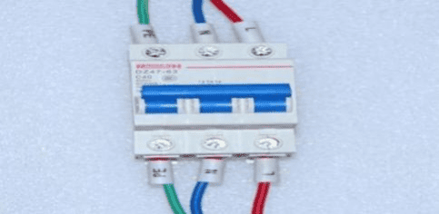
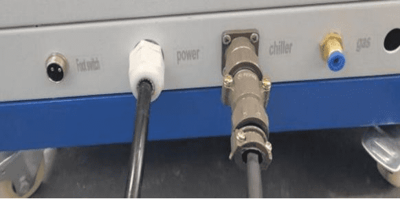
1) Connecting electricity: pay special attention to the red wire for the fire,
the yellow wire for the ground and the blue wire for the zero wire.
The others are phase wires see the diagram below.
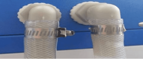
2) Water connection: Connect the chiller water pipe to the main machine, there are two water connections,
not divided into left and right, as shown in Figure 2.2 below.
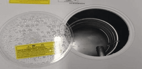
3) Add water: open the lid of the chiller and add pure or distilled water, as shown in Figure 2.3
2.4 Installation Notes.
1) Position the main cabinet correctly, brake the castor brakes,
adjust the basic level of the table and lock it in place.
2) Please appoint a person with sufficient knowledge and experience of
lasers and laser devices to be the facility manager.
(3) The unit must be installed in a fixed horizontal location without inclination; tilting or tipping
the unit will cause a malfunction.
(4) The installation and adjustment of this system is carried out by our professional staff.
(5) Please operate switches and buttons carefully by hand,
reckless operation or operation with objects such as screwdrivers
or pen tips can cause equipment failure or breakage.
(6) Please be careful to operate the switches and buttons one by one
in order to avoid switching multiple switches at the same time causing equipment failure.
2.5 Optical system commissioning
(1)Commissioning precautions
(Special Note: It is strictly forbidden to move the light path section without the light path adjustment)
●The coating layer of optical components is susceptible to dust contamination
and exposure of optical components to air is avoided as far as possible.
●Avoid fumes coming into contact with the optics on the optical base if
the laser hits a nearby target.
●Do not touch the surface of the optics with your hands; ifnecessary,
you must wear a film finger cover.
●Optics should be wiped with high purity anhydrous ethanol
and optical wiping paper ifrequired.
●When holding lenses and lenses, you should only touch the edges of it.
●Before moving the lens or lenses, please observe the direction in
which the lenses or lenses are mounted.
●Wear protective glasses when welding or dimming and avoid looking directly at the laser.
●Avoid putting your eyes in the diode laser’s optical path and
if you are sure that this is necessary, the diode laser power must be switched off.
●When observing the burned shape of the photo paper or
the red light position during dimming at , stop the light output and switch off the light lock.
(2)Precautions before opening the top cover of the casing or operating the pump chamber
Before opening the top cover of the casing or operating the pump room,
the generator air switch must be turned off, and after 5 minutes, use a multimeter to measure
the voltage between the positive and negative poles of the capacitor of the energy storage tank,
and the voltage must drop below 5V.
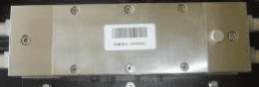
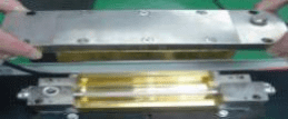
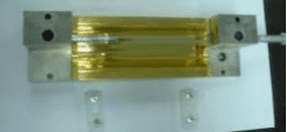
2.5.1 Lasers and optical systems
The structure of the laser and optical system components is shown in the diagram
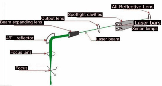
2.5.2 Xenon lamps
The electrical energy is converted into laser energy, which “excites” the laser working substance, i.e., provides energy. This machine uses a heavy
Complex frequency pulsed xenon lamp with cooling of the electrodes
and the ceramic chamber during operation.
2.5.3 Laser bars
Converting light energy into laser energy, this machine uses Nd:YAG crystals as the working substance.
2.5.4 Spotlight cavity
Focusing | reflecting lamp-pumped light onto the laser crystal.
2.5.5 Resonant lenses
Consists of an output mirror and a synoptic mirror, which provides optical feedback and allows
the light to be released in a large laser beam, creating a high intensity.
Laser output. The machine uses a parallel planar cavity, consisting of a plane mirror with an optical glass medium.
2.5.6 Beam expanders
Enlarges the beam diameter and improves the quality of focus. And by adjusting the distance between the two
lenses of the expander, you can fine-tune
The height of the laser focus.
2.5.7 Reflectors
Turn the laser beam direction to 90 degrees downwards and fine tune it
by adjusting the position and angle of the reflector
Position of the laser focus, where the cross-coordinate lines of the microscope overlap.
2.5.8 Gathering lenses
Focusing a parallel laser beam to a single point (i.e., the focal point)
2.5.9 Other components
High voltage electrode, insulated base plate, positioning bracket, adjustable diaphragm holder, laser mounting bracket.
Chapter 3 Jewelry Laser Welding Machine Use and Operation
3.1 Preparation and inspection prior to use
After the installation and commissioning of the equipment is completed, please check whether
the main control cabinet, electrical parts and other parts of the whole machine are firmly connected
and make sure that the wiring of each part is correct and free from looseness, etc.
The user needs to pay attention to
the following information before using the equipment.
( 1) Please use the equipment in strict compliance with the safety
precautions mentioned in these operating instructions to ensure that the machine
and personnel are working in a safe
and potentially hazardous environment.
(2) Check whether the wires between the various parts of the machine
are connected correctly and reliably according to the requirements,
water pipes, navigation plugs, power supplies, etc.
Remove all unrelated objects to ensure that the working environment of the machine meets
the basic requirements.
(3) The operator of the DGW-200 series jewelry laser welding machine must
be strictly trained and should follow the operating procedures strictly.
3.2 Equipment start-up
1 、 Wiring is as shown in Figure 3. 1 and is connected accordingly to the requirements.
2 、 After ensuring that the mains power is on, close the power air switch as shown in Figure 3.2.
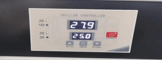
3 、 Turn on the key switch of the main unit, and at the same
time you can hear the sound of water flowing
and the pump running, as shown in Figure 3.3.
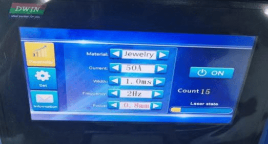
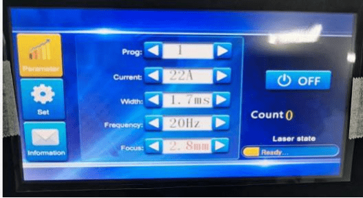
4 、After the equipment is powered on, click ON on the touch screen, you will hear the sound of
the contactor sucking in,
wait for 1 minute for the successful preheating display OFF,
you can adjust the process parameters and carry out welding, Figure 4.4 Host operation interface.
3.3 Shutdown procedure
1. Click OFF on the touch screen and wait 15 seconds.
2. Turn off the equipment vac.
Chapter 4 Maintenance, servicing and troubleshooting
To ensure the normal use of laser welding machines, routine maintenance of
the equipment should be carried out. Laser welding machines are precision equipment
and should be maintained with extra care
4.1 Cleaning of equipment
Before and after each work, firstly, clean the environment, make the ground dry and clean.
Then make sure that the equipment is clean, including the outer surface of the case,
the observation system, the work surface, etc. should be free of debris and clean,
and the protective lenses should be kept clean.
4.2 Maintenance of the cooling system
The main maintenance of the cooling system is to regularly check
the cooling water quality,
if the water quality becomes poor, cloudy, transparency deteriorates,
clean the filter, should be replaced in time with new water.
Regularly check the amount of water stored in the water tank,
if the amount of water stored is insufficient it should be added in time.
This system is recommended to use deionised water or pure water.
Check regularly for leaks at each water pipe interface and tighten
the screws there until no water is leaking.
When water leaks from the seal between the xenon lamp and
the laser bar and the cavity, the main cause is deformation or ageing of the rubber seal,
and water still leaks after tightening the screws,
the rubber ring should be carefully checked and replaced with a spare rubber ring if it has failed.
4.3 Maintenance of the laser system
1) Cleaning the optical path
The internal optical path of the laser system, with its closed design, does not generally need to be cleaned .
If necessary, this can be done as follows: wipe the front and rear optics with lens paper or
with alcohol to keep the surface clean. When wiping, take extra care not to damage the surface by using strong force .
2) Xenon lamp replacement
Xenon lamps should be replaced at regular intervals, usually around 5 million uses.
When the output of the Nd3+: YAG laser is significantly weakened or when
the xenon lamp is difficult to ignite, then a new xenon lamp should be considered.
The procedure is as follows: Switch off the power and wait 10 minutes before opening
the top cover.Open the laser chamber drain switch, drain the water and then lock
the drain switch in place. See diagram below.
Then remove the lamp cable locking screws and the insulating
protective sleeve at both ends of the pump chamber,
as well as the top cover screws. See picture below
Remove the screws of the lamp pressure ring at both ends of
the pump cavity and remove the xenon lamp to one side,
if the lamp fits too closely with the cavity, a few drops of acetone or
alcohol lubrication can be applied around the rubber seal.
When pulling out the xenon lamp, care must be taken not to force
the lamp so that it does not break. See diagram below
The replacement xenon lamp is inserted from the xenon lamp out direction,
install the seals and lamp pressure ring at both ends to ensure that the
end face is pressed and the xenon lamp is in the middle, the installation is removed to reverse the process.
Once installed, turn on the cooling circulating water
and carefully check the connection between the lamp and the concentrator cavity for leaks.
Only when it is ensured that no water is leaking can
the laser power be switched on and the laser readjusted.
4.4 Cyclical maintenance
Table 1 Daily maintenance items
Daily Maintenance
| Serial number | Projects | Methods | Objectives | Remarks |
| 1 | Cleaning of the housing and external equipment | Wipe surface dust with a clean cotton cloth | Cleaning | |
| 2 | Cleaning of protective lenses | Remove the lenses and clean them with a long fiber skimmer soaked in 99.5% or more pure alcohol. | Oil-free, dust-free | If there are cracks or spots, they should be replaced and installed with the uncoated surface facing the direction of the flame splash. |
Table 2 Weekly maintenance items
Weekly Maintenance
| Serial number | Projects | Methods | Objectives | Remarks |
| 1 | Checking the water level in the small water tank | The water level should be between the marked tank levels (MIN to MAX) | Normal water level | |
| 2 | Checking the water level of the chiller | The water level should be between the marked level of the tank (2/3 to 4/5) | ||
| 3 | Checking temperature protection | Turn the temperature switch to below the current temperature after switching on and the power supply should trip. | Protection of normal | |
| 4 | Checking flow protection | Plugging the internal circulation hose after switching on reduces water flow and the power supply should trip. | Protection of normal | |
| 5 | Cleaning filters |
Chapter 5 Transport and Storage
5.1 Methods and precautions for transport and shipment
During the transport of the equipment, please note the following to avoid accidents.
a)It is forbidden to deflect or turn the machine upside down during lifting and transport.
b)Lifting and transport may affect the laser light path and will need to be re-commissioned before use.
c)When the machine is not in use for a long period of time, disconnect all external electrical connections from the machine and keep the optical components clean.
d)When transported over long distances, it must not be packed in open cabins or vehicles,
and if stored in open storage, it must not be stored with flammable, explosive or corrosive substances,
and must not be exposed to rain, snow or other liquids or mechanical damage.
e)During transport, the foot cups need to be fully stowed.
5.2 Storage considerations
The equipment should be stored with the following in mind
f) The equipment should be stored in its original packing box.
The ambient temperature of the warehouse where the equipment is stored is: 0°C – 40°C and the relative humidity is: 20% – 80%.
g) It is not permitted to store the equipment together with various harmful gases, flammable and explosive substances and corrosive substances.
h) The storage location should be free from strong mechanical vibrations, shocks and strong magnetic fields.