
3in1 Handheld Fiber Laser Welding/Cleaning/Cutting Machine
Instructions
1 Security Information
This user manual provides you with important information on 3in1 Handheld Laser Welding Machine safety,
operation, maintenance and other aspects. So please read this user manual carefully before using this product. In order to ensure safe operation and optimal operation of the product,
please observe the following precautions and warnings as well as other information in the manual.
1. 1 Laser Safety Level
According to the European standard EN 60825- 1, clause 9,
this series of lasers belong to four types of laser instruments.
The product emits laser radiation with a wavelength of 1080 or 1080 nm, and the light power emitted by the output head is greater than 100W ~ 2000W (depending on the type).
Direct or indirect exposure to such light intensity can cause damage to the eyes or skin.
Although the radiation is invisible, the beam can cause irreversible damage to the retina or cornea.
Appropriate and certified laser protective glasses must be worn throughout the operation of the laser.
1. 2 Operating Environment
The basic operating environment of the laser is as follows:
3in1 Handheld Laser Welding Machine 1 Laser source operating environment
| Model | DGWF-HR1000/DGWF-HR2000/DGWF-HR1500 |
| Power supply voltage (V) | 220±20% V AC50/60Hz |
| Power supply capacity (kW) | 4 |
| Placement environment | Flatness, no vibration and impact |
| Working environment temperature (℃) | 10~40 |
| Working environment humidity (%) | <70 |
Warning:
1) To ensure reliable grounding before using lasers.
2) The laser output head is connected with the output optical cable. When using, please check the laser output head carefully to prevent dust or other pollution.
When cleaning the laser output head, please use special lens paper.
3) If the laser is not used according to the method specified in this manual, the laser may be in abnormal working condition and cause damage.
4) When the laser is in operation, it is forbidden to install the laser output head.
5) Do not look directly at the laser output head. When operating the laser,
make sure to wear laser to protect the eye.
6) Do not expose the product to high humidity (humidity > 95%).
- 1 Other safety precautions
1) When the laser is in operation, do not look directly at the laser output head.
2) Do not use fiber laser in dark or dark environment.
3) Please strictly follow the laser manual to operate the laser,
otherwise any damage caused by the laser will not be guaranteed.
4) There is no built-in accessory for the laser. All repairs should be carried out by Intouchray staff.
In order to prevent electric shocks, please do not damage the label and uncover the lid,
otherwise any damage to the laser will not be guaranteed.
1. 1 Optical Safety
If the laser output head has dust, the lens will be burned out when the light comes out.
Do not output the laser without the protective cap of the laser output head being opened.
If not, the laser output lens or crystal will be burned down.
1.2 Electrical Safety
1) Please grounding the laser through the PE wire in the power line,
and ensure that the grounding is firm and reliable.
The ground disconnection of the laser will cause the shell of the laser to be charged,
which may lead to the breakdown of the laser.
Personal injury of operator.
2) Ensure the normal supply of AC voltage.
Wrong wiring or power supply voltage will cause the laser to be indispensable.
Restoration damage.
3in1 Handheld Fiber Laser Welding Machine 2 Machine Structure
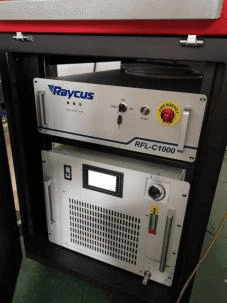
2. 1 Equipment Composition
It consists of laser source, built-in laser water cooler and welding handgun.


performance.
Water chiller interface
Water cooler outlet connected to laser inlet
Water chiller inlet connected to laser outlet
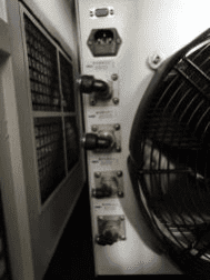
There is also a water-cooled interface between the optical fiber laser head and the hand-held gun head.

Attention to cold water use
The water chiller uses pure water without any impurities, otherwise it will cause trouble.
The condyle cold water must be replaced once in 1-2 months.
2.2 Hand gun for welding < swing head >
Safety Lock Ground Wire < Yellow Strip Clamp >
Attention to Connect with GAS
Before starting to weld/clean/cut, please make sure the machine has connected with Argon gas or Nitrogen gas.
3in1 Handheld Fiber Laser Welding Machine 3 Operation Instruction
3. 1 Start up
Turn on the leakage protection switch after power is connected
(the water cooler is turned on by default, and the water cooler must
be turned on first if the water cooler is not turned on).

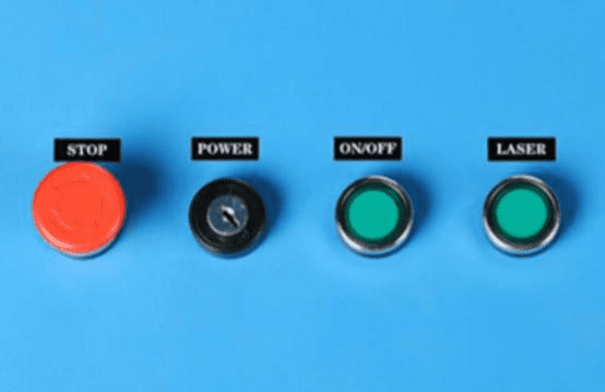
1) Turn on the emergency stop switch and turn on
the key switch to start the whole power supply.
2) Because some lasers have self-checking system,
the laser button should be turned on first (waiting 10S).
3) Welding System Button Open.
Safety lock grounding wire clamp to worktable, hand-held gun head contact,
protection lock open before welding.
3.2 Turn off
1) Laser Button and Welding System Button First Closed.
2) Turn off the key switch.
3) Leakage Protection Switch Closed.
3.3 Touch screen operation instructions
Pre-use debugging and parameter setting
Before the first use, the following debugging Settings should be made to ensure that the equipment is
installed correctly and without failure. First check whether the red light comes out from the center of the
copper nozzle, as shown below.
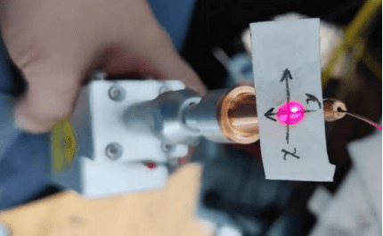
Be sure to ensure personal safety before operation. Only red light can be emitted, not laser.
Stick a piece of translucent adhesive paper on the copper mouth of the welding joint to check
whether the red light comes out from the center of the copper mouth. If it is in the center, no
adjustment is needed. If there is any deviation, adjust the parameters on the touch screen for
correction, as shown in the following figure.


To complete the above Settings, you also need to set the wire feeding parameters.
Click Advanced
Parameter Settings on the main interface and click the wire feeding parameter
button at the bottom of
the advanced parameter interface to enter the wire feeding parameter interface,
as shown in the figure below.

If there are no special requirements, set the above parameters and click “Save”.
Parameter explanation:
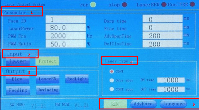
- Parameter Column
A. Para ID:You can select a parameter group number to
edit multiple groups of parameters in advance, and then
select the required parameter group number to work.
B. Laser Power:Set laser power percentage, adjustable from 0 to 100%
C. PWM Fre:Set the frequency of PWM modulation signal,
adjustable from 0 to 200000HZ.
D. PWM Ratio:Set the duty cycle of PWM modulation signal cycle, 0- 100% adjustable.
E. Dorp Time:Set the slow rise time for the light release phase.
F. Rise Time:Set the slow down time at the end of welding.
G. AdvOpenTime:Set the air blowing time before welding starts.
H. DelClosTime:Set the time for maintaining air blowing after welding,
the time unit is ms. - Input Column
Laser:Display the on/off status of the handheld head switch signal.
Protect:Display on/off status of protection signal. - Output Column
Blow/laser En/Red light are used to show the shape of the output port. You can click the output corresponding signal when the welding process stops. - Laser Type
CONT:Continuous laser
Once Spot:Light shooting for one spot
CONT Spot:Light shooting as continuous spots - At the bottom of the screen are the current software and hardware version numbers,
advanced parameters , and language switch buttons.
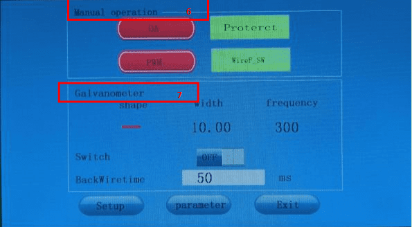
6.Manual Operation
Click advanced parameters to enter the advanced parameter setting interface.
DA: Turn on/off DA signal.
PWM: turn on/off PWM signal.
Protection signal: turn on/off protection signal.
Wire feed switch: turn on/off wire feed switch signal.
- Galvanometer
The shape of the galvanometer can be adjusted to produce light patterns.
There’ re 5 patterns “ ” 、“∞”、“8”、“一”、“ 丨”,Width can be set to 0-5;
The frequency can be set to 0-999; Galvanometer
switch switches the galvanometer on and off.
‘BackWireTime’ should be time delay after turning off laser source.

8.The original password of the software is 111111.

9.Click the “Galvanometer Setting” box at the lower left of the advanced parameter interface to enter the galvanometer setting interface as shown below.
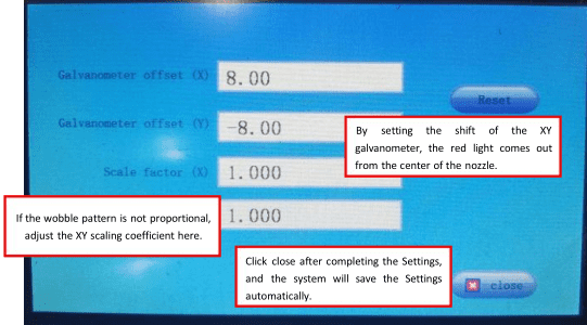
Galvanometer offset: the galvanometer offset button can control
the offset of the optical origin of the galvanometer,
and the offset of the galvanometer offset (X/Y) controls the offset of
the horizontal axis and the 16/ 19 vertical axis of the origin respectively,
with the range of -5-5mm;
Back: can adjust the offset to zero;
Scale factor: the multiple of adjustment that can be amplified, ranging from 0.5 to 2;
Off: Return to the initial main screen.
3.4 Cleaning Application
(1)Cleaning
applications require a larger motor swing Angle to obtain a larger cleaning range,
so it is necessary to remove the front part of the nozzle as shown in the figure below.
And make sure there’s gas blowing out when cleaning.
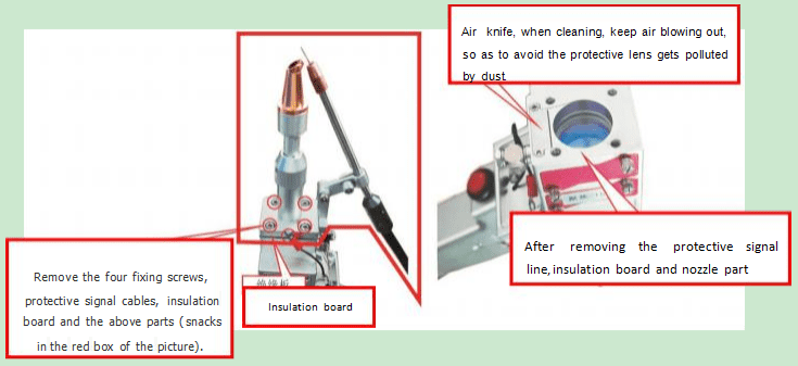
Note: When cleaning, air flow should be kept out to
avoid dust pollution of the protective lens.
**Have a clean cotton swab and anhydrous alcohol ready to wipe
if any contamination occurs during lens replacement.

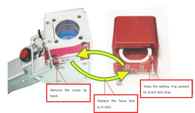
(2) Cleaning applications require a wide range of telephoto depth,
requiring replacement of F=500 lense, which come with
the lens drawer case and drawer lens assembly.
The replacement of the lens needs to be carried out in a clean
and dust-free environment to avoid lens pollution.
If there is pollution, it is necessary to gently wipe the incident surface
and exit surface of the focal lens with a dust-free cotton
swab dipped in alcohol-free essence, and wipe it clean.
Replace the lens as shown below.
(3) Basic parameters:


It is recommended to use horizontal “8” for cleaning shape,
width value below 45, frequency below 200.
Under the condition of F=500, the maximum range of
cleaning is 135mm horizontally and 50mm vertically,
exceeding the range may cause heat in hand held hair,
which may be damaged in serious cases.
3.5 Welding Application
(1)Typical wire feeding welding, before the operation of
the protection signal grounding clamp on the workpiece,
take 1000 watt laser to send 1 mm 304 stainless steel wire,
wire feeding speed 15mm/s protection gas flow 10L/min as an example,
according to the following interface parameters can be set.


**Wire feeding welding effect
(2)If there is no need for wire feeding welding, just turn off the power of wire feeder.
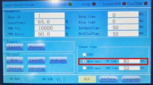
(3) Spot welding application, like1000 watt laser, no wire feeding, protect gas flow is 10L/min, set the interface parameters according to the following:


3.6 Cutting Application
Cutting applications need to adjust the air pressure to 8Kg/cm² to 12Kg/cm²,
remove the wire feeding bracket and replace the welding nozzle with
the cutting nozzle, the cutting nozzle hole is relatively small,
if the red light can not come out of the nozzle hole,
it is necessary to enter the galvanometer to set the
interface to fine-tune the offset of the galvanometer.
Refer to “** Pre-use debugging and parameter setting ”.
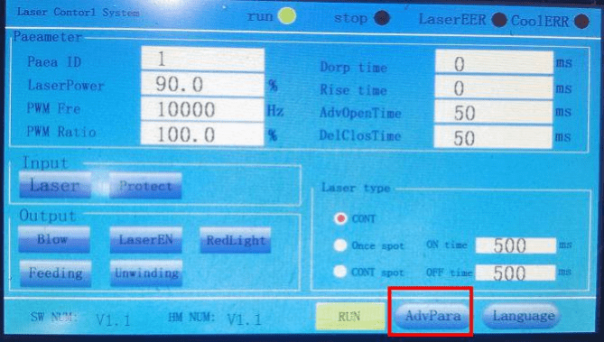
Due to the small aperture of the cutting nozzle, it is necessary to carefully adjust the value of XY offset many times to make the red light come out from the center of the nozzle. Click “Close” after setting, and the system will automatically save the parameters. Set the following parameters on
the home screen and advanced parameter screen.

Control the cutting speed according to the thickness of the material when cutting,
the thinner the material can be cut faster, the hand speed should be uniform when operating,
if the cutting is not straight or the ideal shape can be done.
3.7 Replacement of lens consumables

Caution: Do not touch the high cleanliness area of the laser lens with bare hands.
Dust and stolen goods on the lens may cause scorched and damaged laser lens.
Contact the non-sensitive area of the lens only when wearing protective gloves.
Turn off the laser power when replacing the lens.
3in1 Handheld Laser Welding Machine 4 The Role of Protective Gas
In laser welding, shielding gas will affect the weld formation, quality, penetration and width.
In most cases, blowing shielding gas will have a positive impact on the weld,
but it may also bring adverse effects.
4.1 Positive role
1) Proper blowing of shielding gas can effectively protect weld
pool from being oxidized or reduced.
2) Correct blowing of protective gas can effectively reduce the spatter during welding.
3) Proper blowing of protective gas can make weld pool spread evenly during solidification
and make weld shape uniform and beautiful.
4) Proper injection of protective gas can effectively reduce
the shielding effect of metal vapor plume or plasma cloud on
laser and increase the effective utilization rate of laser.
5) Correct blowing of protective gas can effectively reduce the porosity of weld.
As long as the type of gas, flow rate of gas and blowing mode are selected correctly,
the ideal effect can be achieved.
However, incorrect use of shielding gas will also have adverse effects on welding.
4.2 Adverse effects
1) incorrect blowing of protective gas may lead to worsening of weld seam:
2) Choosing the wrong kind of gas may lead to cracks in the weld,
and may also lead to the decrease of the mechanical properties of the weld.
3) Choosing the wrong gas inflow rate may lead to more serious oxidation of weld seam
(whether too large or too small flow rate), as well as serious collapse of
weld seam or uneven formation of weld pool metal caused by external force interference.
4) Choosing the wrong gas injection method will result in the weld not reaching
the protective effect or even almost no protective effect,
or have a negative impact on the weld forming.
5) Injection of protective gas will have a certain impact on the weld penetration,
especially when thin plate welding, it will reduce the weld penetration.
4.3 Types of Protective Gases
The main protective gases used in laser welding are N2, Ar and He.
Their physical and chemical properties are different, so their effects on welds are also different.
- Nitrogen N2
The ionization energy of N2 is moderate, higher than that of Ar and lower than that of He.
Under the action of laser, the ionization degree of N2 is general,
which can reduce the formation of plasma cloud and increase
the effective utilization rate of laser. Nitrogen can react with aluminium alloy
and carbon steel at a certain temperature to produce nitride,
which will improve the brittleness and toughness of weld,
and have a greater adverse impact on the mechanical properties of weld joint.
Therefore, it is not recommended to use nitrogen to protect
the weld of aluminium alloy and carbon steel.
Nitride produced by chemical reaction between nitrogen and
stainless steel can improve the strength of weld joint, which will be conducive to
the improvement of mechanical properties of weld, so nitrogen can
be used as protective gas in welding stainless steel. - Argon Air
The ionization energy of Ar is relatively low,
and the ionization degree is high under the action of laser,
which is not conducive to controlling the formation of plasma clouds,
and will have a certain impact on the effective utilization rate of laser.
However, the activity of Ar is very low, it is difficult to react with common metals,
and the cost of Ar is not high. In addition, the density of Ar is high,
which is beneficial to the formation of plasma clouds. Sinking above
the weld pool can better protect the weld pool,
so it can be used as conventional protective gas. - Helium He
He has the highest ionization energy,
the ionization degree is very low under the action of laser,
and it can control the formation of plasma cloud very well.
Laser can act on metal very well, and he activity is very low,
and it does not react with metal chemically.
He is a good weld protection gas, but the cost of He is too high,
and it is generally mass-produced.
The product will not use the gas. He is generally used for scientific research
or for products with very high added value.